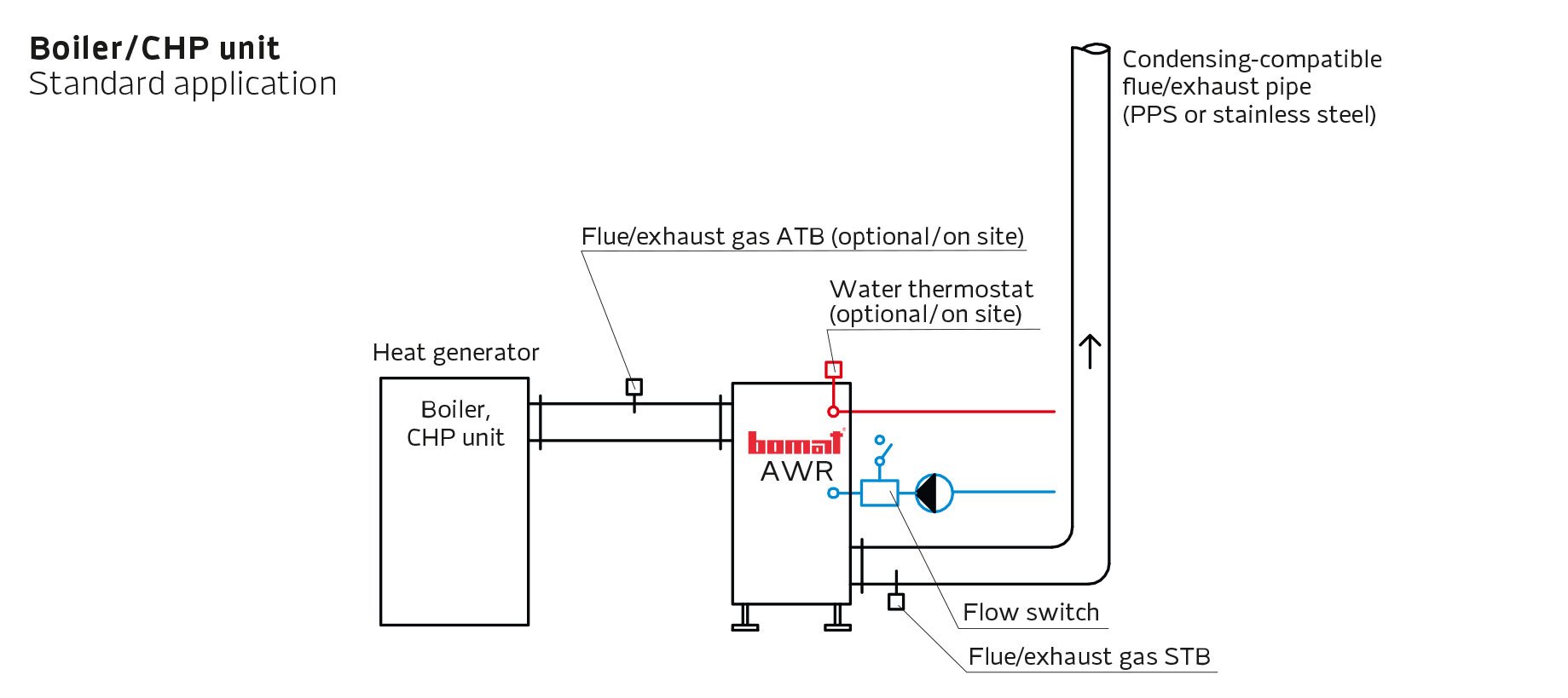
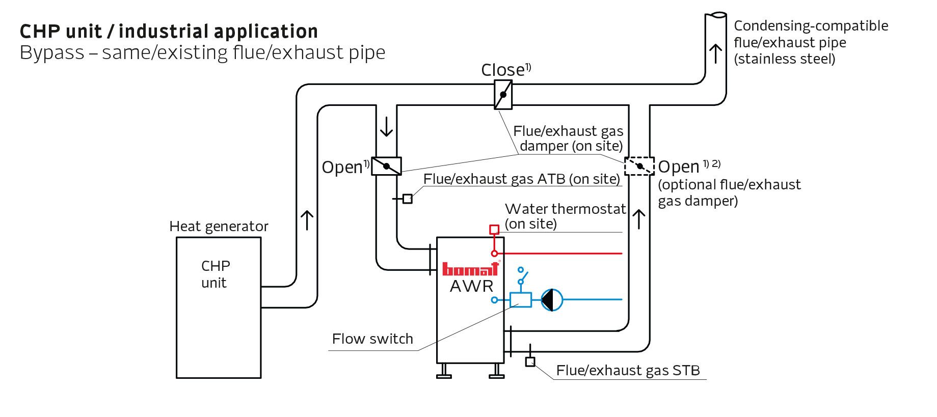
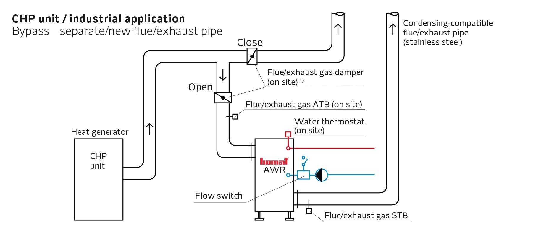
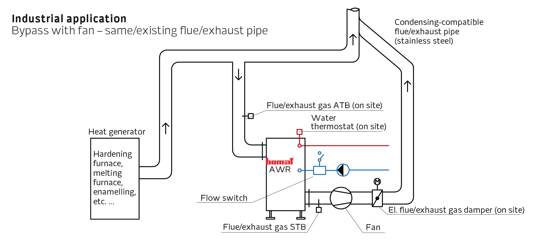
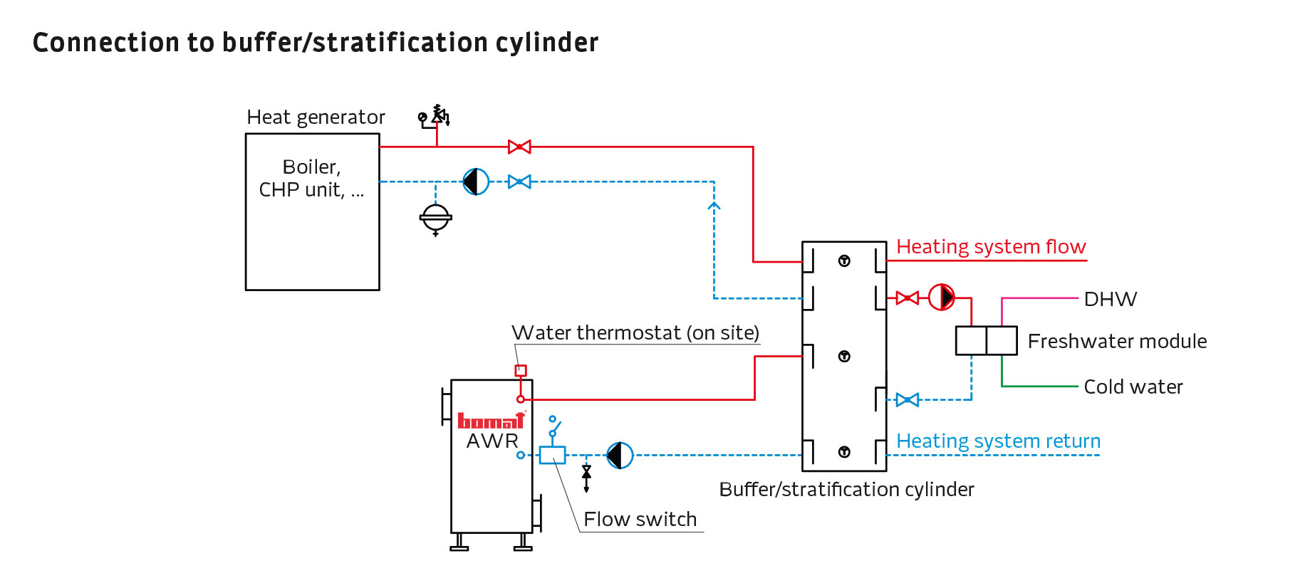
Application examples for exhaust gas heat exchangers
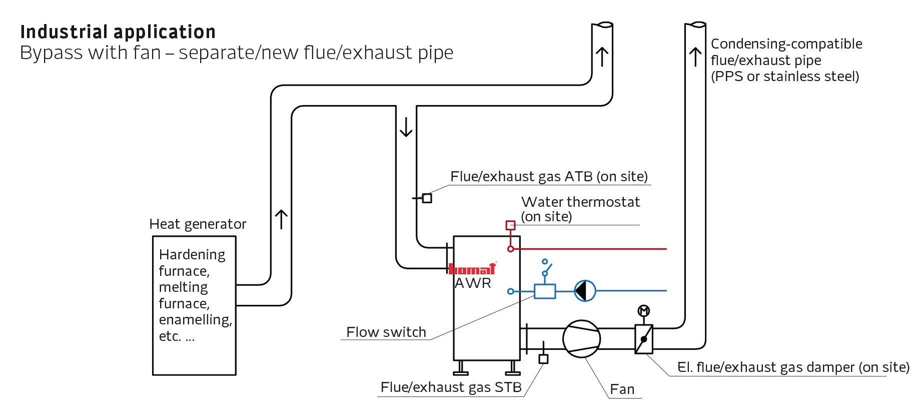
ATB = Flue/exhaust gas temperature limiter
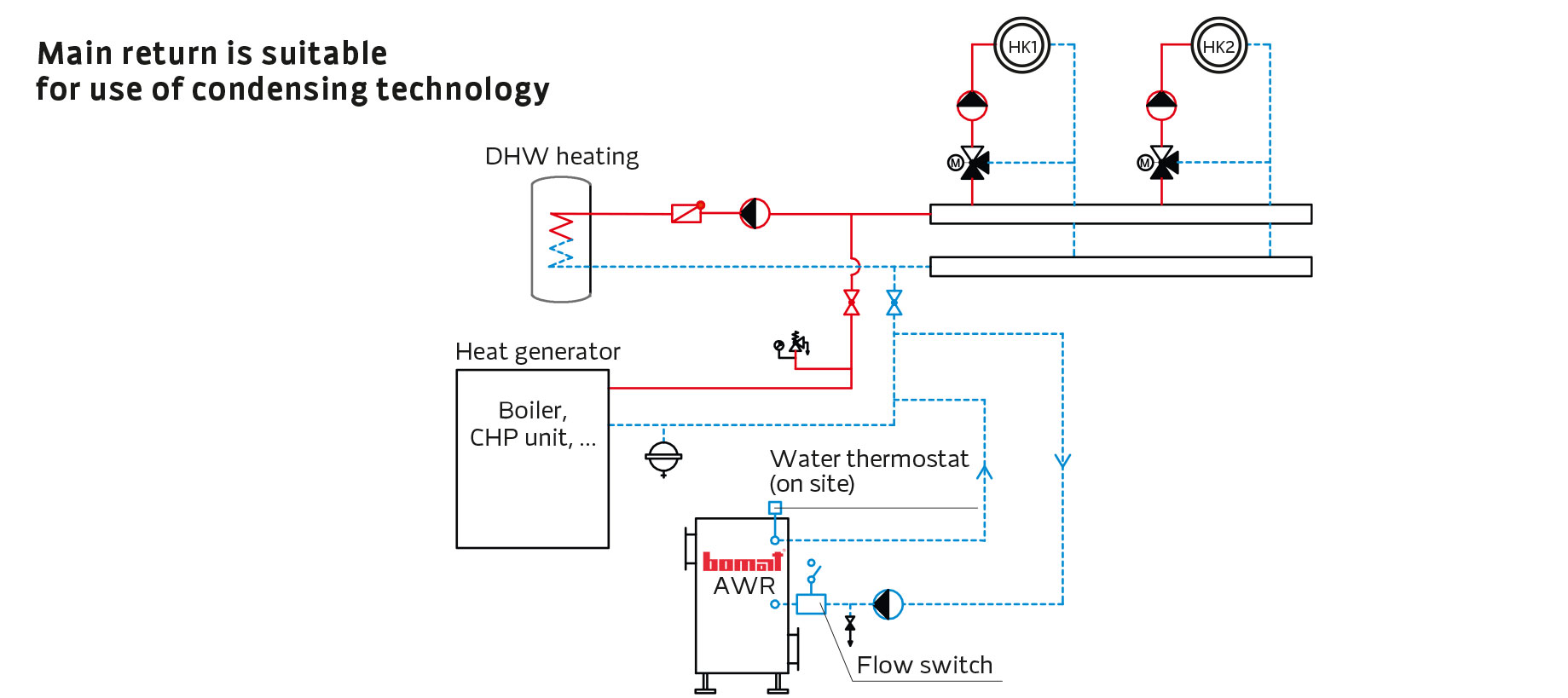
HK = Heating circuit
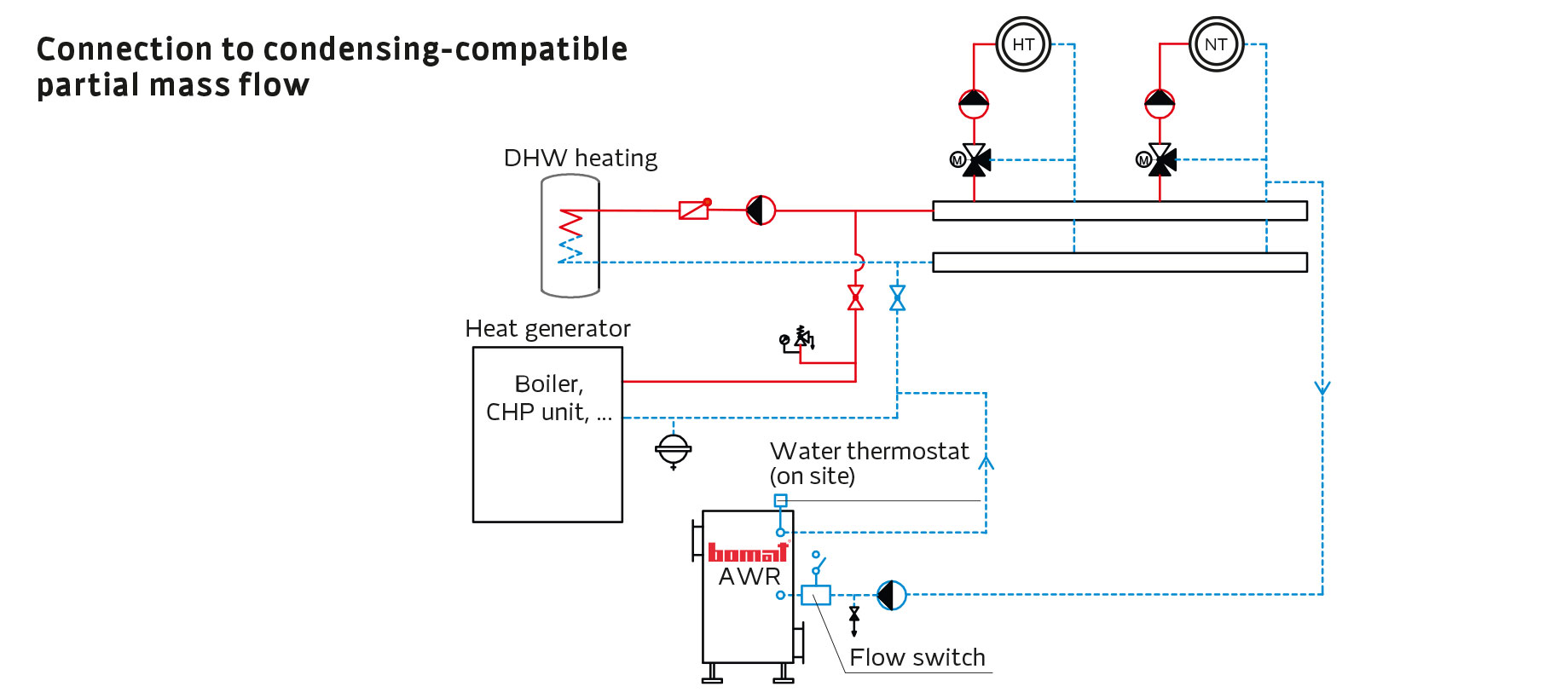
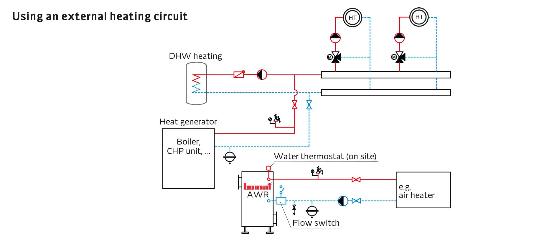
HT = High temperature heating circuit
M = Motor/actuator
NT = Low temperature heating circuit
STB = High limit safety cut-out
HK = Heating circuit
HT = High temperature heating circuit
M = Motor/actuator
NT = Low temperature heating circuit
STB = High limit safety cut-out
1) The flue/exhaust gas path must always be open in one direction. A CHP unit must not be operated with dampers closed.
2) This damper must only be closed during maintenance.
2) This damper must only be closed during maintenance.
Please note:
The colder the return temperature at the heat exchanger inlet, the higher the energy yield.
The colder the return temperature at the heat exchanger inlet, the higher the energy yield.
Note:
The images shown are intended as examples only and merely provide a greatly simplified illustration.
The images shown are intended as examples only and merely provide a greatly simplified illustration.
Quotation request
We are happy to provide an individual quote for your project. To request a quotation, please complete our form.

